The focal spot is one of the most crucial components that determine image quality in industrial x-ray inspection systems. Simply put, the focal spot refers to the area on the anode of the x-ray tube where electrons hit and cause x-rays to be emitted. The size and geometry of this focal spot directly impact the achievable image resolution and sensitivity of flaws for a given x-ray inspection application.
Table of Contents
ToggleOverview of the Focal Spot in X-ray Tubes
Within an x-ray tube, electrons are generated and accelerated across a high-voltage gap, hitting the angled anode target and rapidly slowing down. This rapid deceleration of electrons causes the emission of x-rays from the anode material. The specific area on the anode where the electrons hit and come to rest is known as the focal spot.
The focal spot acts as an effective x-ray source for the inspection system. X-rays diverge and radiate outward from this small region on the anode. This focal area’s size, shape, and intensity distribution fundamentally determine the geometric properties and resolution capabilities of the resulting x-ray beam used for imaging.
Focal Spot Size and Image Resolution
The size of the focal spot is perhaps the most important characteristic for determining the maximum achievable image resolution in x-ray inspection. This is because the focal spot acts as the x-ray source, analogous to the filament in a light bulb acting as a visible light source.
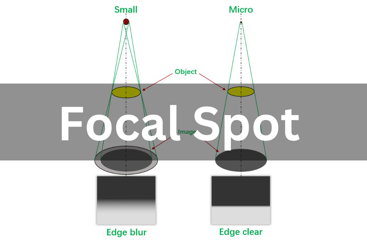
A larger focal spot produces a divergent X-ray beam spanning a wider area on the detector. This causes unsharpness and geometric blurring in the resulting radiograph image.
A small micro-sized focal spot emits a narrowly focused X-ray beam. This allows more defined imaging with reduced blurring and sharper resolution of small features in the test object.
Smaller focal spots enable sharper image resolution and the ability to detect smaller flaws. This is because a smaller focal area minimizes geometric blurring and spreading of the x-ray beam as it passes through the inspected object. Think of it like focusing sunlight through a small pinhole versus a large opening. Therefore, a smaller focal spot is desired to gain higher image detail and resolution in X-ray inspection applications. Typically, focal spots under 1 mm diameter are used for industrial imaging purposes.
However, decreasing focal spot size also reduces X-ray flux. So very small micro-focus spots may require higher exposure times. So there is a tradeoff between resolution and penetration capabilities when selecting focal spot size. An optimal balance is necessary to gain adequately sharp images at acceptable inspection speeds.
Typical Focal Spot Sizes Used in X-ray Inspection
Most industrial x-ray inspection tubes have a fixed focal spot size in the range of 0.4 mm to 1.0 mm. However, some x-ray tubes and inspection systems provide multiple focal spots to switch between or even allow continuous adjustment of the focal spot dimensions.
Some key focal spot size ranges include:
- Large focal spots – 1.0 to 5.0 mm: Used for high penetration in very thick or dense objects. Resolution is compromised but scan times can be faster.
- Medium focal spots – 0.4 to 1.0 mm: The most common range for general-purpose industrial inspection. Provides good penetration with reasonable resolved detail.
- Small focal spots – 0.1 to 0.4 mm: Enables high-resolution imaging for small flaw detection at the cost of penetration. Common for electronics, PCBs, foods, thin plastics.
- Microfocus spots – 0.01 to 0.1 mm: Highest magnification inspection capabilities but only usable with thin and low-density materials.
So in summary, the 0.4 to 1.0 mm range is suitable for most industrial x-ray inspection applications as a good balance between resolution, penetration, and scan times. But specific applications may require larger or smaller focal spot sizes.
Optimizing Focal Spot Size for Specific Applications
The optimal focal spot size depends greatly on the particular inspection application, including material thickness, part density, flaw sizes of interest, and any resolution requirements.
For example, a small 0.1 mm spot could provide excellent resolution but lack the penetration for inspecting thick castings or welds. A larger 1 mm spot may better serve such an application.
Conversely, a tiny microfocus spot under 0.1 mm would provide enormous magnification for examining PCB solder joints but could not image through denser plastics or rubber products.
So the focal spot should be matched to the application for optimal results. Other factors like part placement, geometry magnification, and detector characteristics also influence the imaging system resolution. But the focal spot remains one of the most fundamental determinants of resolving capability.
Factors Affecting Focal Spot Performance
Besides size, other focal spot parameters also impact performance:
- Geometry and uniformity of electron distribution
- Thermal loading capacity to withstand heat
- Electron beam steering to maintain a consistent position
Well-engineered X-ray tubes optimize these characteristics to deliver stable micro-focus spots that enable the highest image resolutions possible for critical inspection needs.
Effect of Focal Spot Shape and Uniformity
In addition to size, the shape and uniformity of the focal spot also affect image quality. The focal area typically has a rectangular or elliptical shape due to the angled target surface. Non-uniformities can cause distortions in the image.
A rounded, symmetrical, and uniform focal spot is ideal to minimize these effects. Defining specifications not just for focal spot size but also for shape and evenness helps ensure performance.
Some x-ray targets approximate a larger, uniform focal area using multiple small focal spots. This helps average out non-uniformities compared to a single, solid focal spot of the same size.
Importance of Focal Spot Measurement and Standards
Given the importance of the focal spot, proper measurement and standardized specifications are critical for comparing x-ray tubes and inspection systems.
There are two primary methods used:
- Pinhole camera – A simple pinhole optics arrangement images the focal spot, allowing its size and shape to be directly measured.
- Slit camera – Uses a narrow slit to characterize focal spot width and length. More accurate than pinhole cameras.
International standards for focal spot sizes and measurement techniques have been established to enable consistent specifications between vendors and technologies. For example:
- IEC 60522 – International standard for focal spot measurements.
- EN 12543 – European standards for nondestructive testing, including x-ray focal spots.
- ASTM E1165 – Test method for focal spot sizes using pinhole and slit cameras.
X-ray Tube Design Factors Influencing Focal Spot
The x-ray tube design greatly influences the achievable focal spot size and stability during tube operation. Some key design factors include:
- Anode angle – Steep-angled targets help direct electrons to a smaller focal area. But too steep increases heat loading. Common angles range from 5° to 45°.
- Anode rotation – Spinning anodes spread the heat load and allow higher power density for smaller spots. But rotating structures require more complex tubes.
- Electron optics – Electrostatic and electromagnetic focusing lenses and deflectors shape the electron beam profile and trajectory to refine the focal area.
- Target materials – Different anode materials have varying thermal properties and melting points that constrain the feasible focal spot dimensions.
Ongoing advances in x-ray tube engineering continue to enable smaller yet more powerful focal spots to improve industrial inspection capabilities while minimizing tradeoffs.
How to determine the ideal focal spot size for your specific inspection needs
The ideal focal spot is a matter of optimization based on inspection goals, part parameters, image quality needs, and production throughput considerations. Proper focal spot selection is key to achieving your target sensitivity and resolution in X-ray inspection.
Here are some tips on determining the ideal focal spot size for your specific X-ray inspection application:
- Assess the smallest features, defects or variations you need to detect in the test objects. This will determine the required image resolution.
- Consider the material thickness and density you need to penetrate. Thicker and denser parts may need more X-ray flux, indicating a larger focal spot.
- Evaluate acceptable inspection time per part. Smaller focal spots mean longer exposure times may be needed for adequate throughput.
- Test different focal spot settings using indicator objects with representative features. Compare image sharpness, contrast and noise.
- Select the smallest focal spot size that provides satisfactory detection of the smallest critical flaws within your throughput requirements.
- Balance magnification against focal spot blurring. Higher magnification also enlarges the blurring effect.
- For large-part inspections, a distributed multi-focal spot source can improve resolution across the field of view.
- Consider microfocus tubes with switchable dual focal spots for flexibility in optimizing resolution vs inspection time.
- Discuss specific inspection objectives with your X-ray equipment vendor for guidance on matching focal spot size to your application.
- Plan for future inspection needs and technology improvements that may require smaller focal spots.
Inspection System Requirements Based on Focal Spot Size
The specific size of the focal spot, along with the x-ray tube power and detector characteristics, determines the capabilities of an x-ray inspection system. Some general guidelines include:
Large Focal Spots
- Thick, dense objects
- Fast scan times
- Lower magnifications
- Large flaws and defects
Medium Focal Spots
- General purpose inspection
- Reasonable scan times
- Moderate magnifications
- Medium flaw sizes
Small Focal Spots
- High magnifications
- Thin low-density materials
- Slow scan times
- Very small defects
Microfocus Spots
- Highest magnifications
- Low-density objects only
- Very long scans
- Tiny flaws and features
So when selecting an x-ray inspection system, the focal spot size should be considered relative to the specific application requirements, along with all the other imaging chain components and specifications.
Conclusion
The focal spot is a critical parameter defining the capabilities of x-ray inspection systems. A smaller focal spot enables higher resolution imaging but reduces penetration. The optimal size balances magnification against material thickness and density. Focal spot size specifications, shape, and measurement standards allow meaningful comparisons between x-ray tubes and overall inspection systems. When selecting the appropriate x-ray inspection equipment, the focal spot size should be carefully considered against application needs for optimal flaw detection performance.
FAQs about Focal Spots in X-ray Inspection
Here are some common questions and answers about focal spots in x-ray inspection systems:
Q: What is the typical focal spot size for industrial CT scanning?
A: In industrial CT, focal spots ranging from 0.5mm to 1mm are typical, providing a good balance of resolution and penetration for dimensional metrology and defect analysis. However, small parts may use focal spots down to 0.2mm for higher resolution scanning.
Q: Can the focal spot size be changed dynamically during an x-ray inspection?
A: Some advanced x-ray tubes allow continuously variable or multiple fixed focal spots. This allows adjusting the spot size to optimize different phases of the scan, such as using a larger spot for initial penetration followed by a smaller spot for higher resolution imaging.
Q: How does focal spot size affect the required x-ray power?
A: As focal spots get smaller, the total x-ray flux emitted decreases, requiring higher tube power to maintain penetration. So smaller spots require more powerful x-ray tubes to compensate for the lost output.
Q: What causes non-uniformities and asymmetries in the focal spot shape?
A: Factors like uneven electron beam distributions, target surface defects, and thermal distortions can cause non-uniform emission intensity across the focal spot area, reducing image consistency.
Q: Can focal spots get too small for effective x-ray inspection?
A: There are diminishing returns below 0.1mm, especially under 0.01mm focal spots. Limitations like thermal diffusion, electron scattering, and geometric effects at very small sizes prevent further meaningful gains in resolved detail.